Timing 201 #3: The Case of the Parasitic PLL - Part 1
Author: Kevin G. Smith
Introduction
Anyone who has had training or experience in high frequency electronics is familiar with the concepts of parasitic capacitance and inductance. These are the unintended “hidden schematic” components that you get when assembling physically realizable circuits. Modeling these elements explicitly may be necessary depending on the application and desired accuracy.
It turns out that an independent oscillator can couple energy in to a Phase-Locked Loop’s (PLL’s) VCO so as to influence or even take over the PLL’s output frequency and phase. This is the case of the parasitic PLL. It is a special case of injection as described below.
In this post, I will review the basic theory and modeling for this phenomenon. My interest is not in walking through the derivations but rather noting the highlights of the results. This basic bench-level knowledge of injection is useful when designing or applying oscillators and PLLs. Cited references are listed at the end for further study. In the next post I will discuss how to measure injection sensitivity and provide for its mitigation.
Motivation
Injection locking can actually be useful in certain specific applications such as injection-locked frequency dividers. See Razavi (2004) for example. However, there are several reasons why unintentional injection in PLL frequency synthesis is undesirable:
● Injection pulling can increase low offset frequency phase noise and phase jitter.
● The injection locked oscillator’s stability is determined by the interferer.
● The parasitic coupling path or paths may be poorly controlled over the operating environment.
● Finally, even a synchronous interferer can increase absolute jitter in Type II PLLs as the integrator attempts to erroneously correct for phase error.
Unless otherwise noted, this post assumes that the applications of interest involve PLLs which rely on LC resonant tank oscillators. Such circuits are in common use and subject to power supply coupling and external interference. Their Q or quality factor is high enough to yield reasonably good phase noise performance but low enough that injection can be an issue. The emphasis will be on a board level perspective though the same general principles may be applied at lower integration levels.
Oscillator Injection
Injection pulling or locking refers to when one independent oscillator disturbs or locks the frequency and phase of another independent near-synchronous oscillator. Using crosstalk terminology, the victim oscillator’s frequency is pulled by the aggressor or interferer’s frequency. In the extreme, one oscillator is pulled all the way to lock at another oscillator’s frequency.
It is well known that oscillators in close proximity tend to lock to each other. The figure below gives the basic idea. Mechanical injection locking was first observed in pendulum clocks by Dutch scientist Christiaan Huygens in the 17th century. For a modern revisit of this work, see this online paper from Georgia Tech: http://schatzlab.gatech.edu/Library/Bennett2002.pdf.
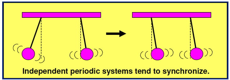
This is commonly demonstrated in educational settings using metronomes on shared rolling or fixed platforms. See for example http://salt.uaa.alaska.edu/physics_public/metro.html. I have done this myself and it’s a neat demonstration.
Analogous behavior can happen in electronics when working with tuned oscillator circuits. Two classic papers on this subject are Adler (1946) and Kurokawa (1973).
Independent Oscillators
In this context, the term independent oscillator can refer to either asynchronous clocks that are very close (or harmonically close) in frequency or to synchronous clocks that are out of phase.
Further, the notion of independence can be extended to synchronous clocks with different phase noise characteristics. The most important example of the latter case is a PLL’s input and output clock domains. Consider a noisy input clock provided to a narrow bandwidth “clean-up” PLL that yields the same frequency output clock. The jitter attenuated output is synchronous to the input clock but independent from a phase noise point of view.
Basic Injection Theory
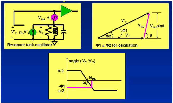
My favorite practical treatment on this topic is in Wolaver (1991) and I lean heavily on his work in what follows. Consider the following figures adapted from his book. I use “INJ” subscripts for injection quantities and “T” subscripts for tank quantities for clarity.
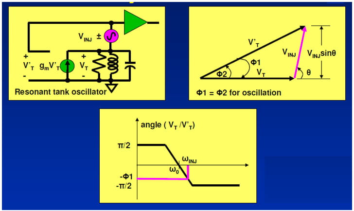
In these figures, the following terms apply:
ω0 = oscillation frequency without injection
ωINJ = oscillation frequency with injection
Θ = phase of VINJ relative to VT
VINJ = injected voltage
VT = tank voltage
V’T = tank voltage + injected voltage where V’T is shifted in phase from VT by F2
For sustained oscillation the tank circuit must yield a compensating phase shift -Θ1 from VT to V’T and Θ1 = Θ2. The phase of the transfer function VT/ V’T is plotted in the bottom figure. The bottom line is that an injected voltage will result in a phase shift in the oscillator loop.
Oscillator Injection Lock Range
By assuming that VINJ << VT, Wolaver derived an injection constant or gain where injection acts like a 1st order PLL. Below is a version of Wolaver’s derivation for KINJ with one term re-cast as the square root of a power ratio.

In these figures, the following terms apply:
PINJ = Power, injected
PT = Power, tank circuit
Q = loaded Quality factor of the tank circuit
ω0 = oscillation frequency without injection
KINJ = injection constant or gain
The derivation suggests several important take-aways, all called out in the figure.
1. The higher the nominal tank frequency the greater the injection susceptibility.
2. The higher the Q the lower the injection susceptibility.
3. The injection lock range increases with greater injection interference.
4. In principle, any oscillator can be injection locked.
The model below is adapted from Wolaver’s simplest small signal model for a PLL with injection. This version breaks out the injection constant contributions where the angle α represents the phase difference between the injected signal and the input signal.
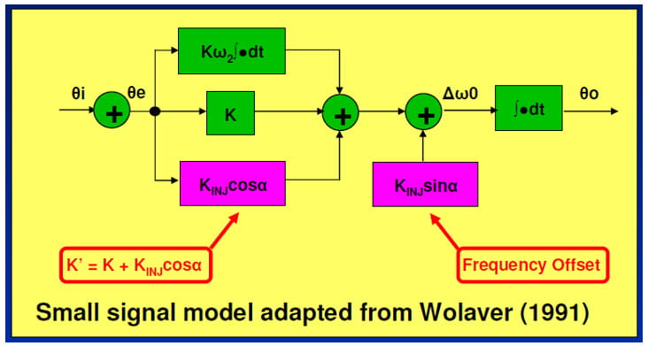
There are two important features to note in this model.
● Injection has changed the approximate PLL bandwidth (BW) from K to K’ = K + KINJ * cosα
● To minimize injection effects, we want KINJ << K
This last item is most important. Wolaver suggests K > 4 * KINJ. All else being equal, relatively NB (narrow bandwidth) PLLs are more susceptible.
Looking ahead to Part 2, the relationship between the nominal (uninjected) and injected PLL BWs will prove useful both in terms of troubleshooting and mitigation. You may recall a previous blog post Timing 101 #5: The Case of the PLL’s VCO High Pass Transfer Function. It pointed out that a relatively wide bandwidth PLL can be used to attenuate VCO intrinsic phase noise. Likewise, a wide bandwidth PLL is also useful to suppress external influences on the VCO such as injection pulling or locking.
References
Some of the material covered here was presented at the Austin Conference on Integrated Systems and Circuits (ACISC) in 2009. If you are interested, you can email me to request a copy of the paper “Practical Issues Measuring and Minimizing Injection Pulling in Board-level Oscillator and PLL Applications” and accompanying slides.
As mentioned previously, the best practical overall book treatment I am familiar with is in Wolaver’s text:
● D.H. Wolaver, Phase-Locked Loop Circuit Design, 1991, Prentice-Hall, pp. 97-104.
This is a slim volume for a PLL book but it punches well above its weight in terms of information.
Here are several foundational papers worth reading on the topic of injection.
● R. Adler, “A Study of Locking Phenomena in Oscillators,” Proc. IRE and Waves and Electrons, vol. 34 (June 1946), pp. 351-357.
● K. Kurokawa, "Injection Locking of Microwave Solid-State Oscillators," Proc, IEEE 61, 1386 (1973).
● B. Razavi, “A Study of Injection Pulling and Locking in Oscillators,” IEEE J. Solid-State Circuits, vol. 39, pp. 1415-1424, September 2004.
If you have favorite references you would like to share, please pass them along to me.
Conclusion
I hope you have enjoyed this Timing 201 article. Next time, I will follow-up on measuring and minimizing injection sensitivity.
As always, if you have topic suggestions, or there are questions you would like answered, appropriate for this blog, please send them to kevin.smith@skyworksinc.com with the words Timing 201 in the subject line. I will give them consideration and see if I can fit them in. Thanks for reading. Keep calm and clock on.
Cheers,
Kevin
[Note: This blog article was originally posted online in January 2020. It has been lightly edited, and updated to reflect Skyworks Solutions’ acquisition of Silicon Labs’ Infrastructure and Automotive business, completed on July 26, 2021. The Timing 101 series continued for 12 articles and was superseded by the Timing 201 series.]

By Kevin G. Smith
Sr. Principal Applications Engineer


