hero home image description

Automotive - Lidar, Radar, and Camera Systems

Automotive Lidar, Radar, and Camera Systems

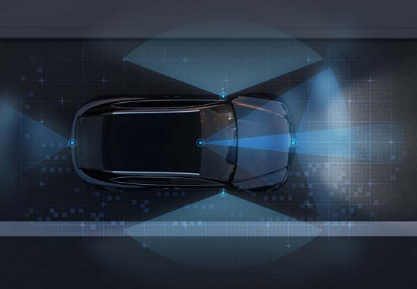
Vehicles classified as Level3, Level4, or Level5 must be fully aware of the surrounding environment, track the status and movement of objects in all directions, and use that information to navigate the vehicle. A combination of lidar, radar, and cameras are used to create short, mid, and long range 3D maps of a vehicle’s environment and surrounding objects. These systems continuously detect and transmit large amounts of real time data via high bandwidth Ethernet to an automated driving central compute platform. The data is processed using sophisticated software algorithms to identify what the objects are, what the trajectory the objects have, how fast they are moving, ultimately forming instantaneous 3D maps of the vehicle’s surrounding in order to make decisions on how to navigate the vehicle.

Car Radar
  • Frequency Flexible, integrated timing solutions

Benefits of a silicon-based timing solution


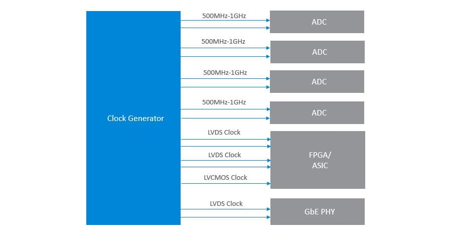
Lidar, radar, and camera systems all have advantages in one way or another, which is why a combination of them is typically used in Level 3, Level 4, and Level 5 enabled automated vehicles. Most designs use high-end FPGA platforms and/or high-speed processor platforms that feature high bandwidth 56G or 112G SerDes. Specialty sensor ICs and high-speed ADCs/DACs are also commonly used, as well as 1GbE or 10GbE to transmit the data to the automated driving central compute platform. Each of these major design components requires integer and fractional related reference clocks ranging from 100 MHz to 1 GHz, at various differential output formats, with RMS phase jitter below 300fs. Meeting these requirements using a quartz oscillator solution provides challenges of reliability, cost, and sourcing. Alternatively, clock generators provide the capability to synthesize a combination of integer and fractional related reference clock frequencies up to 1GHz, feature programmable output format drivers, support RMS phase jitter performance as low as 100 fs, and also provided in-system programming that can be used to alter one or more output clock frequencies in small incremental steps.

We recommend the following when considering timing solutions for your design:

Summarize The Clock Tree: Start by outlining all the reference clocks, jitter performance requirements, and associated timing features needed within your design. This is commonly known as a clock tree. Each individual design will have its own unique clock tree, but will commonly need a combination of single-ended clocks and differential clocks with different levels of jitter performance requirements. Having this summary will be useful when starting to identify a timing solution.

Frequency Flexibility: Lidar designs commonly use high bandwidth FPGAs, ASICs, and high-speed ADCs, all of which require low-jitter, high frequency (100MHz - 1GHz) differential output clocks. Our patented MultiSynth output divider technology provides 0ppm synthesis error on both integer and fractional related output frequencies on up to 12 outputs while maintaining industry best jitter performance. Each output can be individually set to a specific frequency and format level, providing the ability to consolidate high-frequency clocks into a single clock generator. Our clock generators also offer in-system I2C frequency programming, as well as a DCO mode, providing the capability to fine-tune the reference clocks.

​ 

Reliability: Quartz crystal and oscillator components are mechanical devices that are prone to shock and vibration failure. Even AEC-Q200 rated devices have high FIT rates, oftentimes being the components with the highest point of failure rating in system design. Rather than adding more and more quartz crystal and oscillator components to a system design not only increases the bill of materials and total system cost but also increases reliability concerns as quartz elements are prone to shock and vibration failure. A better approach is to integrate that quartz crystal and oscillator components into a clock generator solution. Taking this approach greatly reduces the FIT rate associated with the timing portion of the design, while also providing numerous other features that can be beneficial to clock tree design, such as spread spectrum for EMI/EMC mitigation, frequency selection, and fault monitoring.

Feature Set and Integration: Our clock generators come equipped with many features that can simplify your design, such as spread spectrum for EMI reduction on differential PCIe clocks, frequency selection capability on audio clocks, hardware output enable control, multi-profile selection, and redundant clock input capability with fault detection. Achieving low jitter performance is always a high priority, so our clock generators include on-chip LDOs on all power pins, resulting in industry best PSNR performance. Suppressing external power supply and board-level noise on-chip greatly reduces the number of external components needed for power filtering, reducing board space and cost, and ensures that output clock jitter performance meetings the datasheet specification limits.

Customization: Our ClockBuilder Pro software tool guides you through an easy, step-by-step process to generate a configuration file specific to your clock tree requirements. When the configuration file is complete, ClockBuilder Pro can assign a customized part number specific to your design, provide an associated datasheet addendum, and allow you to save it for future use.