Timing 201 #4: The Case of the Parasitic PLL - Part 2
Author: Kevin G. Smith
Introduction
In the last Timing 201 post, I discussed the parasitic Phase-Locked Loop (PLL) in which an independent oscillator can couple energy in to a PLL’s VCO so as to influence or even take over the PLL’s output frequency and phase. I then reviewed some basic injection theory, including the concept of injection lock range.
Given the amount of material I would like to cover, I am going to follow-up that post with two more articles. This installment, Part 2, will discuss how to minimize injection sensitivity generally. Part 3, to come later, will cover the topic of measuring injection sensitivity.
A Brief Review
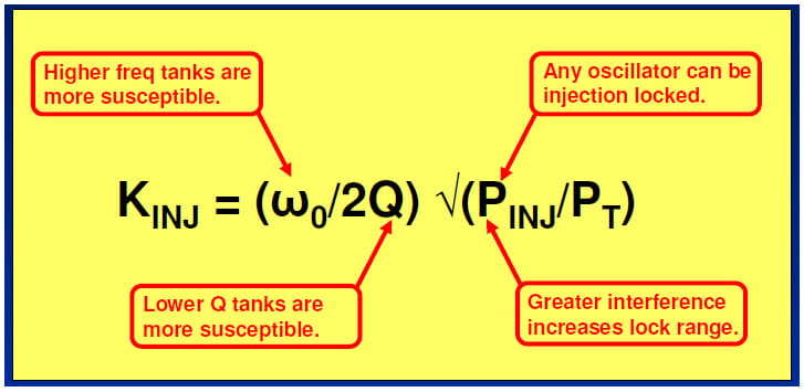
Per the last article, injection pulling or locking refers to when one independent oscillator disturbs or locks the frequency and phase of another independent near-synchronous oscillator. We then reviewed injection theory after Wolaver (1991) culminating in this equation with the important take-aways noted.
ILBW (Injection Lock Bandwidth)
Wolaver treated the injection constant or gain KINJ as the injection lock range. It is useful to regard this lock range as the Injection Lock Bandwidth (ILBW) to contrast it with the PLL’s loop bandwidth (BW). From here on, I will use this nomenclature. The bottom line is that, in order to minimize the risk of injection locking, we want BW > ILBW. Ideally, BW would be significantly greater than the PLL’s ILBW.
The factors in the formula suggest where we might run in to trouble. For example, LC tank oscillators, especially when integrated, have much lower Q compared to crystal oscillators. Further, the trend is for higher and higher frequency clocks. The resonant tank frequency itself is usually dictated by something on the order of 2 times the maximum 50% duty cycle output clock frequency we would like to support. So we should be on guard for this issue when considering narrow band (NB) and high frequency low-Q VCO tank circuit PLLs.
So why don’t we routinely run in to injection problems today? Well you still can, if you are rolling your own NB discrete synchronous PLLs and especially if you co-locate them. This article series is in part an attempt to warn you of some possible concerns.
Board and IC designers have learned over the years to adopt injection resistant practices and PLL topologies. First, let’s begin by considering some typical injection mechanisms.
Injection Mechanisms
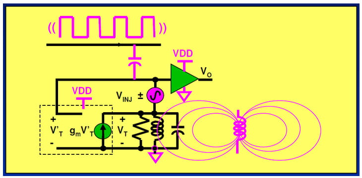
There are several common injection mechanisms in which aggressor oscillator noise may couple in to a tank oscillator circuit. The first two listed are suggested by the figure below:
- Power supply noise transmitted through the PCB or IC substrate
- EM fields directly coupled in to the tank circuit
- Conducted noise via board traces and IC pins
We can mitigate, or reduce the impact, of injection by directly addressing these injection mechanisms and/or by using more injection resistant system-level approaches.
Injection Mitigation via Good EMC Design
Injection can be regarded as a special topic within the field of EMC (Electromagnetic Compatibility). We can minimize injection noise power applied at the tank for each of these mechanisms using good practices for designers cognizant of general Electromagnetic Interference (EMI) issues.
- Power supply noise through PCB or IC substrate
⇨ Power supply bypassing or filtering
- EM fields directly coupling to the tank circuit
⇨ Employing separation and shielding
- Conducted noise via board traces and IC pins
⇨ Applying signal filtering and good PCB layout: planes, short traces, etc.
All of the above methods attack the problem by reducing the strength of the aggressor noise PINJ. However, in addition to these direct approaches, there are some other more systemic ways of minimizing injection problems.
Injection Mitigation via Thoughtful Frequency Planning
You may recall that I mentioned the general problem of injection pulling and locking arises when working with signals and oscillators that are synchronous or nearly so. What do I mean by nearly-synchronous? A SONET application board with lots of clock I/O all running at or near SONET frequencies within a few ppm of each other is a classic example.
One approach, if you have multiple PLLs or clock devices co-located on the same printed circuit board, is to configure them so that the VCO frequencies are asynchronous from each other. For example, consider an application where you have two adjacent Si570 I2C-Programmable XOs on a PCB. You can minimize the risk of injection crosstalk (XTALK) by configuring the devices so that their internal DCOs or Digitally Controlled Oscillators are well off frequency from each other.
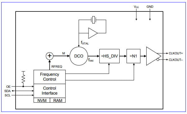
Consider the Si570 Detailed Block Diagram below taken from this datasheet. In the diagram, HS_DIV refers to the DCO High Speed Divider with possible values [4-7, 9, 11]. N1 is the CLKOUT Output Divider with allowed values [1] and [2, 4, 6, …, 27]. Finally, the datasheet constrains the DCO frequency to 4.850 GHz ≤ fosc £ 5.67 GHz. Given these constraints, there can often be multiple frequency plan solutions that output the same clock frequency.
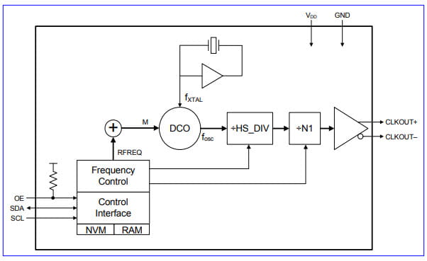
For example, the DCOs can be made significantly asynchronous even when the output clocks are identical in frequency. Here are two valid Si570 configurations that both yield f1 = 155.52 MHz outputs.
- fosc1 = f1 x HS_DIV x N1 = 155.52 MHz x 4 x 8 = 4.976640 GHz.
- fosc2 = f1 x HS_DIV x N1 = 155.52 MHz x 9 x 4 = 5.598720 GHz.
In this instance, each DCO frequency is asynchronous, greatly minimizing the risk of injection XTALK.
Injection Mitigation via Beneficial Clock Architectures
One architectural approach is to simply minimize the number of PLLs, and therefore VCOs, with associated tank circuits, that might be susceptible to injection XTALK.
An example clock generator that minimizes the number of PLLs is the Si5338 I2C-Programmable Any-Frequency, Any-Output Quad Clock Generator. The functional block diagram below is taken from the Si5338 datasheet.
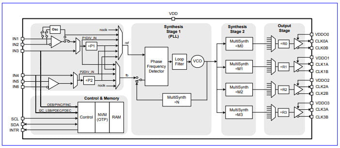
The Si5338 design consists primarily of a single wideband PLL with a bandwidth typically 1.6 MHz, followed by 4 “MultiSynth” dividers which can support four independent output clocks. The MultiSynth dividers are Silicon Labs’ proprietary low jitter fractional dividers that incorporate phase error correction. This whitepaper discusses this approach. Please note that there are other lower jitter clock generators employing similar architectures, with more clock I/O, such as the Si5332.
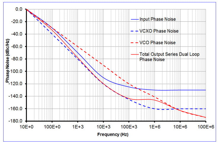
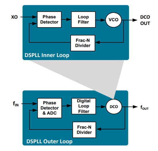
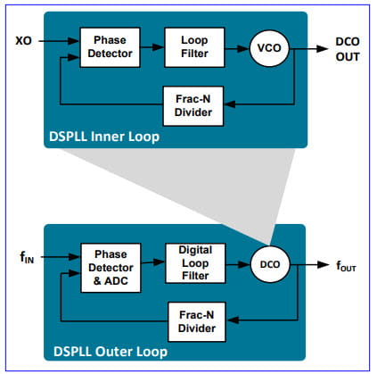
A second injection resistant architectural approach is to embed the potentially susceptible VCO tank circuit in a wideband PLL. (Recall that we want BW > ILBW.) An example jitter attenuator device that improves injection rejection in this way is the Si5380 which uses a nested dual loop architecture as shown in the diagram below. This illustration is taken from the “Optimizing Clock Synthesis in Small Cells and Heterogeneous Networks” whitepaper.
In this topology, the LC tank circuit VCO is integrated in a wideband (fast) inner loop which itself acts as the DCO for a narrowband (slow) outer loop. Please note that the Si5380 has been superseded by the more flexible, higher performance Si5386.
References
The same references that applied to the previous Timing 201 post apply here. They are listed below, for convenience.
Some material covered here was presented at the Austin Conference on Integrated Systems and Circuits (ACISC) in 2009. If you are interested, email me to request a copy of the paper “Practical Issues Measuring and Minimizing Injection Pulling in Board-level Oscillator and PLL Applications” and accompanying slides.
As mentioned previously, the best practical overall book treatment of injection lock that I am familiar with is in Wolaver’s text:
- D.H. Wolaver, Phase-Locked Loop Circuit Design, 1991, Prentice-Hall, pp. 97-104.
This is a slim volume for a PLL book but it punches well above its weight in terms of information.
Here are several foundational papers worth reading on the topic of injection.
- R. Adler, “A Study of Locking Phenomena in Oscillators,” Proc. IRE and Waves and Electrons, vol. 34 (June 1946), pp. 351-357.
- K. Kurokawa, "Injection Locking of Microwave Solid-State Oscillators," Proc, IEEE 61, 1386 (1973).
- B. Razavi, “A Study of Injection Pulling and Locking in Oscillators,” IEEE J. Solid-State Circuits, vol. 39, pp. 1415-1424, September 2004.
If you have favorite references you would like to share, please pass them along to me.
Conclusion
To recap, there are a number of ways that IC, board, and system designers can reduce the risk of injection pulling or injection lock.
- Good EMC Design
- Thoughtful Frequency Planning
- Beneficial Clock Architectures
- Minimize the number of PLLs and therefore VCOs
- Embed susceptible VCOs in a wideband PLL
Looking ahead, it turns out it is often not practical to straightforwardly calculate the ratio of PINJ/PT and therefore KINJ or ILBW. Next time I will review how one may measure ILBW in the lab.
I hope you have enjoyed this Timing 201 article. As always, if you have topic suggestions, or there are questions appropriate for this blog you would like answered, please send them to kevin.smith@skyworksinc.com with the words “Timing 201” in the subject line. I will give them consideration and see if I can fit them in. Thanks for reading. Keep calm and clock on.
Cheers,
Kevin
[Note: This blog article was originally posted online in January 2020. It has been lightly edited, and updated to reflect Skyworks Solutions’ acquisition of Silicon Labs’ Infrastructure and Automotive business, completed on July 26, 2021.]

By Kevin G. Smith
Sr. Principal Applications Engineer


