Timing 201 #5: The Case of the Parasitic PLL - Part 3
Author: Kevin G. Smith
Introduction
As I write this, many of us around the world are working under COVID-19 quarantine conditions. So before diving in, I want to wish all of you and yours the very best of health. Please take care of yourselves out there!
Now to recap so far:
In Part 1 of this series, I discussed the parasitic PLL in which an independent oscillator can couple energy into a Phase-Locked Loop’s (PLL’s) VCO which can impact the PLL’s output frequency and phase. I then reviewed some basic injection theory including the concept of injection lock range. In Part 2, I discussed how to minimize injection sensitivity. In this last and final Part 3, I will discuss the topic of measuring injection sensitivity, and what one can do with that information.
ILBW (Injection Lock Bandwidth)
The figure below was presented in Part 1 and follows Wolaver’s development culminating in this equation with the important takeaways noted.
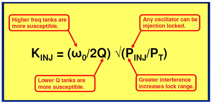
Wolaver treated the injection constant or gain KINJ as the injection lock range. It is useful to think of this lock range as the Injection Lock Bandwidth or ILBW to contrast it with the PLL’s loop bandwidth BW. In order to minimize the risk of injection locking we want
ILBW < BW
In fact, we would prefer for ILBW < BW. A practical empirical rule of thumb we have applied is the following
ILBW ≤ 0.3 * BW
We will apply this rule of thumb in later example calculations.
ILBW Practical Issues
Let’s take another look at Wolaver’s equation for
KINJ as the injection lock range aka the Injection Lock Bandwidth or ILBW. In the annotated figure below I call out some practical issues.
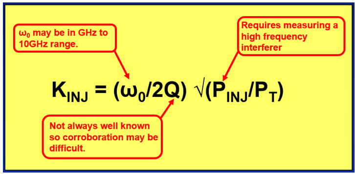
There are several difficulties that may arise when attempting to make direct calculations of this equation based on measurements of the individual factors:
- The quantities Q and the ratio PINJ/PT are not always well known.
- The frequency of the tank circuit fTANK is typically on the order of GHz to 10 GHz or more, which means we will need high frequency sources and probes.
- Probing directly at ICs may be difficult and/or require purpose-built test boards.
- HF scope probes may need calibrating to make measurements directly at fTANK.
Provided one can apply a calibrated high frequency interferer, it is often easier to measure the effective ILBW. The rest of this post will discuss a couple of ideas on how to do this.
ILBW Measurement Approaches
This post will discuss two different measurement approaches summarized in the table below. The first method applies an asynchronous aggressor source and uses the offset spur result measured on a spectrum analyzer to estimate the ILBW. The second method applies a synchronous aggressor source and measures the ILBW directly from a phase noise analyzer.
|
#
|
Method
|
Comments
|
|
1
|
Asynchronous Injection
|
Estimate ILBW indirectly based on spectrum analyzer spurs.
|
|
2
|
Synchronous Injection
|
Measure ILBW directly based on phase noise performance.
|
These methods will be demonstrated using older simpler architecture devices where injection may be conveniently observed. Modern clock devices are generally less susceptible to injection due to architecture, shielding, etc. The examples that follow will give an indication of what you might observe with classic narrow bandwidth single loop PLLs.
PLL Injection Sensitivity – Estimating ILBW via Asynchronous Injection
Using this first approach, we measure the spur that results on the output for a given asynchronous but near-synchronous injection applied to the device. The general idea is to configure the DUT as typical, using an input clock source that does not have significant harmonics at or near the PLL’s VCO frequency. Then apply an interferer or aggressor clock set near the VCO frequency to individual pins and determine the worst case.
The general test set-up used years ago for the Si53xx SONET devices was as follows:
- Configure an Si53xx device for a nominal 622.08 MHz clock output resulting in the tank operating at 2.48832 GHz.
- Apply an input reference clock, e.g. 155.52 MHz, applied single-ended in to one of the CLKIN connectors. A good sinusoidal source is used and then bandpass filtered in order to reject any additional harmonic components in the vicinity of the tank frequency. Thus the only significant interferer at the tank is the one purposely injected.
- An interferer or aggressor clock set to 2.48834 GHz at -20 dBm drives a device pin through an RF connector on a purpose-built PCB designed just for this test. On this board, device pins are AC coupled to RF connectors that are terminated in to 50 Ohms.
- Output clock measurement: The output clock and the resulting offset spur are measured using a spectrum analyzer. For the case where –20 dBm is applied directly as described, the offset spur will be in the –40 to –70 dBc or lower range depending on the device and the pin. Other than the supply pins having typical bypass capacitors, there were no I/O filtering or other injection lock mitigating features used on this test board.
A general comment about probes: One can measure the voltage at device pins using a divide-by-10 high impedance differential probe, even if not specified to operate at the intended frequency, if carefully calibrated. Back when this data was collected the probes available had a 20 dB calibrated loss at 2.5 GHz.
So for a -20 dBm interferer we would expect a signal at the device pins as follows assuming no additional losses.
-20 dBm applied interferer
-20 dB due to divide-by-10 probe
-20 dB due to probe roll off at 2.5 GHz
----
-60 dBm measured at device pins
How can we use this technique to estimate the ILBW or Injection Lock Bandwidth? Here are the steps.
- Apply an finj offset from ftank well outside the loop BW.
In this example, the 20 kHz offset of the interferer is chosen for convenience to insure that the selection of loop BW is irrelevant. Selecting the 800 Hz BW allows one to select an interferer with a lower offset frequency.
- Measure the offset spur Pspur (dBc) versus the output clock.
- Calculate Pspur_tank accounting for any output dividers.
- Extrapolate ILBW for Pspur_tank = 0 dBc per the anticipated injection locking 20 dB/dec slope. (This is effectively calculating an intercept.)
PLL Injection Sensitivity – Example Estimated ILBW Calculations
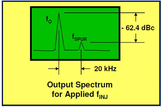
The figure below shows the spectrum for an Si53xx SONET clock device configured for an output of 622.08 MHz together with the resulting injected spur. The DUT used a post VCO output divider N = 4 to yield output frequency f0 = 622.08 MHz. For this device, the DUT VCO frequency or ftank = 622.08 MHz x 4 = 2.48832 GHz.
Here are the example calculations in this instance:
- We applied injection frequency finj = 2.48840 GHz or 80 kHz offset at -20 dBm.
- The resulting output spur frequency fspur = 622.10 MHz or 20 kHz offset at -62.4 dBc.
- Accounting for the N=4 output divider, Pspur_tank = -62.4 dBc + 20*log10(4) = -50.4 dBc.
- Set P_spur_tank – 20*log10 (f_ILBW/f_offset) = 0 dBc and solve for f_ILBW
⇨ -50.4 dBc – 20*log10 (f_ILBW/f_offset) = 0 dBc
⇨ – 20*log10 (f_ILBW/f_offset) = 50.4
⇨ f_ILBW/20kHz = [10^(50.4/-20)]
⇨ f_ILBW = [10^(50.4/-20)] * 20e3
⇨ f_ILBW or simply ILBW = 60.4 Hz
The minimum operating BW for this part is 800 Hz. Applying the rule of thumb ILBW is much less than 0.3 * 800 Hz or 240 Hz. Therefore we do not expect injection lock to be an issue.
Another way of looking at the problem is to ask: For a given loop BW selection how large a spur, referred to the tank frequency, am I allowed to have using the rule of thumb?
Pspur_tank (max allowed) = 20*log10(fILBW/foffset) dBc
= 20*log10(0.3*fBW/foffset) dBc
Using the same example situation as before:
Pspur_tank (max allowed) = 20*log10(0.3*800/20000) dBc
= -38.4 dBc
Injection Lock Tolerance
We can apply the information described above, together with worst case pin data, to estimate how much interfering signal the device pins can tolerate before injection lock may cause jitter to be an issue. The worst case data suggested that the interferer amplitude at a pin may be as low as –50 dBm and yield a spur as high as –44 dBc.
Using this worst case pin assumption, then the worst case spur at the tank would be:
Pspur_tank_wc = -44 dBc + 20*log10(4) = -44 dBc + 12 dB = -32 dBc
Recall that the Pspur_tank (max allowed) for an 800 Hz BW is -38.4 dBc and so we must decrease the allowable interferer signal strength at the pins to –50 dBm – (38.4-32) = -56.4 dBm. As a practical matter, we should then decrease this by at least another 6 dB to add margin. This suggests the following criterion for the Si53xx clock chips:
The interferer strength at a device pin should not exceed –62 dBm.
This conservative criterion means that Si53xx clock devices should not injection lock unless an extraneous 2.5 GHz source can inject a signal > –62 dBm at an individual pin.
What if we had an especially noisy application where this limit was exceeded? If significant interfering energy is present, filtering, attenuation, and good layout can reduce the level of conducted interference on sensitive pins.
PLL Injection Sensitivity – Measuring ILBW via Synchronous Injection
In this second approach, we apply a synchronous interferer and observe the impact of injection lock directly on the phase noise plot.
The figure below illustrates the basic idea.
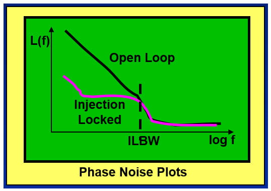
• An injection locked oscillator’s phase noise is reduced from its free running state.
• The intersection of the phase noise plots is the single-sided ILBW.
• This method uses a low phase noise independent synchronous source to directly measure the ILBW for a specific amount of injection.
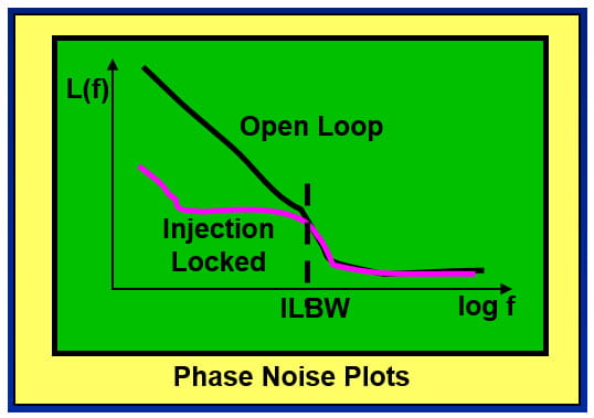
Engineers who are familiar with phase noise plots will recognize that the injection locked oscillator phase noise truly looks “locked” just as if it was in a designed PLL, and not in an incidental or parasitic counterpart.
Evaluation Board Experiments Setup
To demonstrate the phase noise analyzer approach, I used an RF Synthesizer evaluation board which has convenient VCO frequencies for my purposes. The figure below summarizes the test set-up.
In this case however, I did not want to use a purpose-built board or inject an interfering signal at all the pins. Instead, I decided to simply remove the bypass caps and inject the synchronous interferer directly in to the power supply. You can think of this as a high frequency extension to PSRR or Power Supply Rejection Ratio testing. In other words a sort of IPRR or Injection Pulling Rejection Ratio test.
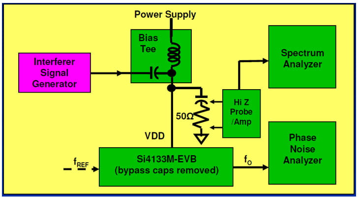
Here are the main points:
- The Device Under Test (DUT) was the venerable Silicon Labs Si4133 which is a dual band RF Synthesizer with Type I PLLs, integrated VCOs, and which works with external inductors.
- The board used was the Si4133M-EVB with power supply bypass capacitors removed.
- The IPRR1MHz measured ≈ 22 dB down to < 0 dB going from f0 = 473 MHz to 1886 MHz.
Evaluation Board Experiments Phase Noise Plots
The phase noise plots below were based on data measured on an old Agilent (now Keysight) JS-500 rack system which is an E5500 superset. One of the features that’s nice about this older equipment is that the user has direct access to the measurement PLL’s loop BW. This allows one to measure very noisy and even open loop phase noise plots.
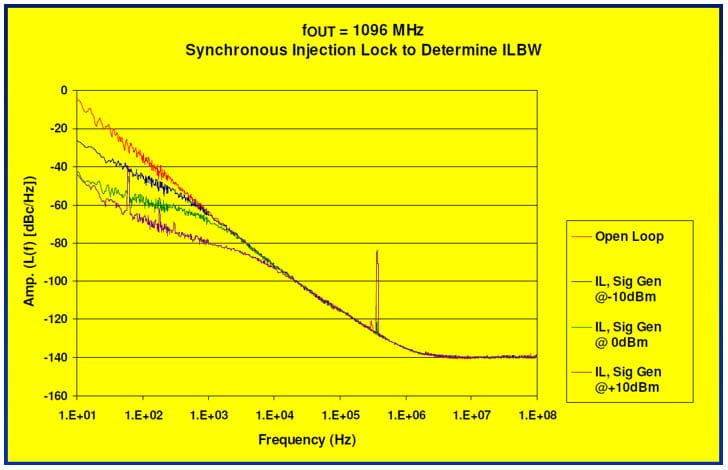
You can read the ILBW directly from the intersection of the locked phase noise plots versus the open loop phase noise plot. As suggested by the Wolaver equation, increasing the power of the injected signal results in a wider ILBW which would restrict the loop bandwidths at which the device would operate.
In these experiments, ILBW only approached 10 kHz even with a +10 dBm synchronous signal injected in to the power supply. Note that the Si4133 is not operated as a jitter attenuator but rather as a clock generator with a good quality TCXO as the reference source or input clock and a typical operating bandwidth ≈ 200 kHz.
Estimated versus Measured ILBW
In the 2009 ACISC paper in the references, I compared both methods applied to the RF Synthesizer and obtained good agreement. See the figure below comparing ILBW as estimated based on 1 MHz offsets versus direct measurement.
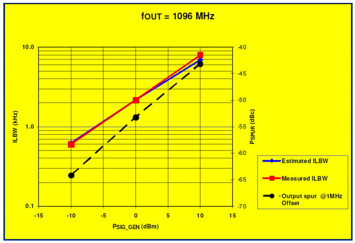
Injection Lock Troubleshooting
Injection lock may be an issue if the device’s clock output jitter is out of spec, cannot be accounted for given the input clock’s phase noise, and the device’s Jitter Transfer Function, and exhibits an unexpected jitter distribution. A suspicious example of the latter would be a bimodal jitter distribution.
A general troubleshooting procedure is listed below. Try each of these items in turn and check to see if the situation improves.
- Widen the selected loop BW. If the input clock has low phase noise and widening the BW improves the output clock jitter then injection lock may be present.
- Assuming the input clock is not excessively noisy, check to make sure that it does not have significant amounts of energy at the tank frequency. If it does, substitute a low phase noise clock, filtered to eliminate components at the tank frequency.
- If there is a follow up PLL with a narrower bandwidth than the DUT try changing the BW relationship either by widening the receiver PLL BW or narrowing the transmitter BW.
- If injection lock is confirmed and items 2-3 have no effect then at this point it is a matter of identifying and turning off other potential aggressor clocks on the board, just as one would with any other EMI investigation.
In the particular case of Si53xx clock ICs, application note AN59 describes generally good layout and filtering practices.
Summary
In this and the previous related blog posts, I have reviewed injection pulling and lock, injection mitigation, and practical measurements. Here are the main points to sum up:
- Two oscillators in close proximity tend to phase lock to each other. This can includes PLL VCOs.
- Injection by independent clocks can impact PLL output phase noise and jitter. In this context, independent clocks can be near-synchronous asynchronous clocks or synchronous out-of-phase clocks.
- Higher frequency and narrow bandwidth single-loop PLLs are more susceptible to injection lock.
- Injection Lock Bandwidth or ILBW is a practical measure of injection sensitivity.
- Reduce ILBW by minimizing the coupling of interferer clocks with a fundamental or harmonic at or very near the PLL’s VCO frequency.
References
The same references that applied to the previous posts apply here. They are repeated again below for convenience.
Some of the material covered here was presented at the Austin Conference on Integrated Systems and Circuits (ACISC) in 2009. If you are interested, you can email me to request a copy of the paper “Practical Issues Measuring and Minimizing Injection Pulling in Board-level Oscillator and PLL Applications” and accompanying slides.
As mentioned previously, the best practical overall book treatment I am familiar with is in Wolaver’s text:
- D.H. Wolaver, Phase-Locked Loop Circuit Design, 1991, Prentice-Hall, pp. 97-104.
This is a slim volume for a PLL book but it punches well above its weight in terms of information.
Here are several foundational papers worth reading on the topic of injection.
- R. Adler, “A Study of Locking Phenomena in Oscillators,” Proc. IRE and Waves and Electrons, vol. 34 (June 1946), pp. 351-357.
- K. Kurokawa, "Injection Locking of Microwave Solid-State Oscillators," Proc, IEEE 61, 1386 (1973).
- B. Razavi, “A Study of Injection Pulling and Locking in Oscillators,” IEEE J. Solid-State Circuits, vol. 39, pp. 1415-1424, September 2004.
If you have favorite references you would like to share, please pass them along to me.
Conclusion
I hope you have enjoyed this Timing 201 series on injection lock.
As always, if you have topic suggestions, or there are questions you would like answered, appropriate for this blog, please send them to kevin.smith@skyworksinc.com with the words Timing 201 in the subject line. I will give them consideration and see if I can fit them in. Thanks for reading. Keep calm and clock on.
Cheers,
Kevin
[Note: This blog article was originally posted online in April 2020. It has been lightly edited, and updated to reflect Skyworks Solutions’ acquisition of Silicon Labs’ Infrastructure and Automotive business, completed on July 26, 2021.]

By Kevin G. Smith
Sr. Principal Applications Engineer


